I tried feeding a line mesh outlining a square into a Make 3D Object node but it didn’t fill the outline. Also the corners were nasty, could do with some chamfering at least (a simple triangle calculation using line width).
I’m going to go ahead and make a FR seeing as Questions are rarely answered on this forum.
:-) I tried to answer as many questions as I could on Kineme when I was learning QC. I don’t know enough to answer questions yet. Feels like the biggest thing holding Vuo back currently is the small user base. More users more sharing and caring. Getting support learning Vuo is going to be critical for anybody so as Vuo grows attending to forums questions will be important. Kineme staff regularly contributed to Kineme especially on their plugins.
It’s probably harder to learn Vuo coming from Quartz Composer: the person expect something to work in a certain way, and it doesn’t. I tried QC maybe six or seven years ago and wasn’t able to wrap my head around it. I began using Vuo a year ago and within a few hours, I had something minimal to show for. I try to promote Vuo any chance I get, but around me, it’s either QC or TouchDesigner…
This is not an answer but it does appear that a general filled polygon is an omission.
The line mesh and line strip mesh, although they don’t meet your needs are behaving as one might expect. Each line segment is treated individually, not as a whole so the chamfering of finite width mesh segments isn’t trivial. … although could be done. One might also like the option for these lines to be finite thickness cylinders.
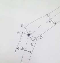
While non-trivial in CPU terms, mathematically using the line width value of the line mesh to calculate the geometry of endpoints at a join and using them to define two triangles that fill to the adjoining line mesh segment shouldn’t be so hard. See image, just add △ABC and △CDE. Or for a radius joint (like Adobe Illustrator offers) draw circle centred at C with diameter W. For 3D points would obviously require a sphere not a circle to do corner radiusing, might make the rendering a bit slow even if it is flattened before it hits a shader how does it get flattened?
I made a composition in QC that used 8 spheres, 12 cylinders and 6 cubes to morph a sphere into a cube and back in various ways, so yeah, been there and it’s not trivial to do by hand.
Alastair … the triangle patching between the meshes where two line join is a little trickier than just filling the missing bit. For lines at sharp angles you may need to trim protruding corners on the large angle side, and actually one wants to trim to avoid coplanar meshes on the small angle side.
And yes, the standard way in 3D is to use cylinders and spheres, but a bit expensive.
I would prefer to see a true line primitive.
you may need to trim protruding corners on the large angle side
Yes didn’t want to complicate my answer with that detail!… Illustrator gives the choice of three corner options and has a parameter input of “limit” for the chamfering one which decides when it will extend out and when it will chamfer.
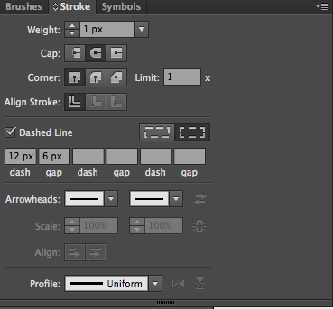
Above shows three strokes of differing widths, colour and corner settings applied to four closed paths. (Note not using identical corners settings for shape, it’s illustrative not a direct comparison with identical settings, note shape 2 is a compound path and shape 3 has corners getting all three treatments with the green stroke set to corner limit of “4x”)
Stokes palette in AI.
actually one wants to trim to avoid coplanar meshes on the small angle side
And yes, coincident coplanar mesh bits would need a “boolean add” operation under the hood or transparency would not work without generating ugly artifacts all over the corners. Maybe even at 100% opacity artifacts/nasty edges would appear. But surely there are OSS libraries that do this kind of thing? Mac Toolbox circa 1990 should be able to do it!
To a limited extent, yes — If the polygon can be created (or flattened from) one of Vuo’s 3D shape nodes. You can see the nodes I mean by searching the node library for “make 3d shape”.
For the example you gave of a filled square, you could use Make 3D Square together with Make Unlit Color Shader. Or for a gradient, use Make Unlit Image Shader and Make Linear/Radial Gradient Image.
These would just be simple shapes without other items you mentioned in your feature request, such as a stroke outline. (For others’ reference, the feature request is here: Make a Polygon Mesh with Fill node.)
Thanks @jstrecker. I really want the ability to at least give 2D points and have Vuo fill and stroke the polygon. If it could construct the polygon using mathematically defined curves even better.
I’m suspecting the work around if my FR doesn’t get up will be to do it in GLSL patch (which is a bit scary for me as it’s a long time since I even dabbled in it, and the learning curve isn’t “a few hours and you’re good to plot a polygon from 100 data-points and use it as a mask”).
I’d pay someone to write that code for me actually :-)
Totally would love an easy way to create a shape on the fly using a point list too ! (personally usually plane 2D rather than 3D too).
Be able to choose fill color or image.
Be able to outline a 3D shape AND layer (For layers, maybe a node like “Add outline to layer”.
On the Polygon node request you say you don’t see your points mentioned in your merged Make a Polygon Mesh with Fill node request. I guess since Jaymie said they’re merged, I may guess your points are merged too ?!
Using Parabox’s Get Mesh Values node along with Smokris Reinterpret 3D object I tried to make a graph like thing. But it is pretty hard since you have to retrieve specific vertices, then merging lists again etc.
PS : remember if you want faster implementation, you can always ask the team for a price estimation for a request and hire them : https://vuo.org/paid-support
I guess even if we could have a shape image which outputs an image as B&W (or layer I forget the difference as it’s been a while!), that could then be used as a mask on anything, an image, a colour, a gradient, a movie. But that does add at least one or two more nodes and potential complications.
You know I’d like to be able to hand the shape node two curves and two lines and just have it determine the enclosed shape defined by those limits (think linear programming in maths) and render it. Would save me having to do maths to work out four intersection points and cull the unnecessary point data from the four limits paths.
God I would love to wake up and be knowing GLSL, conceptually this is piss easy in terms of what GLSL is capable of — but I just don’t know how. And isn’t Vuo for people like me who rather not code too much anyhow? ;-)
If this was a paid project wouldn’t hesitate to reward Vuo with a node commission, but alas just for my graphing work for an NGO atm. Might grow into something I suppose.
Hey @Bodysoulspirit thanks for the composition. A cool approach. I doubt I would have thought of this way of doing it, especially since I didn’t know of the Reinterpret 3D Object node! Very clever. I was thinking i’d have to recombine lists in some way to make a suite of four sided objects or triangles. Smokris’ Reinterpret 3D Object node seems not to generate any ugly artefacts at the joins which is very nice… Why is it that the X values appear to be the randomly moving values not the Y values that are the ones moving on screen? Is there a 90º rotation going on somewhere I can’t see? Thanks again.
@useful_design glad it already helps a bit.
Yes there is a 90° rotation on the Make 3D Object node.
Maybe using Smokris Reinterpret node there could be an even easier way to achieve this.
It was just a quick test and since I don’t know anything about the whole openGL vertices triangles thing I have to play around ;)
Yes I see what you mean with giving points that would close and create a shape. Thinking almost vector design here. Maybe also linked to Feature Request SVG & PDF import
I suppose if any of us know C well, we could read Smokris’ Reinterpret 3D Object source code. (Mine is extremely rudimentary so I’m not game) And we would have the base code for a 3D Polygon from Points node! It must be most of the way there, surely? It does the filling for us. Polygon Node FR is listed as 2 out of 3 for complexity “a few weeks of work”. Maybe a rework of the smokris code could be a stopgap for the next release? It’s just about juggling those points the way @Bodysoulspirit did and combining that with a sub-set of the `Reinterpret 3D Object’ code, am I right @jstrecker?
The bells and whistles of proper 2D polygon corner mitres/radiusing and treatment of compound paths (like the letter “O” or “A” or a circle inside a circle for negative space) could come with an upgrade to the Polygon patch if people started using it and wanting more finesse.
Yeah, I’d really like to fill the polygons in this comp. Btw, @Bodysoulspirit, that comp is awesome! Your approaches to using list tools are inspiring.
I’ll throw this in as an obvious workaround in some cases for a rounded cap – feed a Make Point Mesh with Make Oval Shader the same points as Make Line Strip Mesh. I’d love for someone to tell me how to line them up precisely, because the entire point mesh appears a bit distorted, scale of X/Y axes appear slightly different for me. If you look at Calculate Point Size, you’ll see a formula that reflects how much I am fiddling with the numbers to compensate, still not very good, imo. This was testing for larger line widths at full screen. With smaller line widths, or if you want the points to be conspicuous, then it might be a-ok.
Thanks @jersmi, had a quick look and I’m not sure what you are doing here, I’ll need more time to figure it out. Could you give a quick run through the maths and logic of what it’s doing to make it easier for me please?
I went looking for a quad patch, because I want to do a limited application where I have to lines/curves on a graph and I want to fill the region between them. I have regular X positions/intervals and variable Y values. So I could do it pretty easily iterating through two lists concurrently and making a set of quads, one per pair of points. But I could only find a Quad layer, I’m not sure if that’s that way to go, might have some penalty in making a bunch of layers when I don’t need them. Using @Bodysoulspirit’s method I can substituent Y values into a 3D square of columns using similar thing to what he did in the example above.
Quad Family patch and a few lines of JS and I’d have it nailed in QC, but the QC smooth curve plug-in by Kineme isn’t functional enough for me, it comes with features (kinks/wonks that shouldn’t be there and aren’t in Vuo curves) I can’t accept. I’d like to do in Vuo anyhow, it’s the future.
@jersmi don’t know if you mean you wanted to fill the composition you shared, but using Smokris reinterpret you can fill it, but straight edges, without the round point edges (except for the 2 points on start).
For the oval shaded points size, I don’t know ! But what I don’t understand is that using the same color, the lines and ovals don’t have the same color (you’ll see it better in this modified composition toggling between 2 and 30 points, on 2 points, the left oval point clearly has not the same color, although the line is unlit shaded and the oval shader ignores lightning).
Got it! I forgot about that one. I do have a question about Smokris’ Reinterpret 3D Object and depth stacking order in combination with Combine 3D Objects. In this comp I have the fill (reinterpreted) z translation set to be below the stroke, but Combine 3D Objects stacking order appears to override it? Any clarification?
And that’s a nice example you put up in the Composition Gallery!
@useful_design I’m quite sure you understand the concept here, see attached comp. Make Parametric Points is simply feeding the same point data to Make Line Strip Mesh and Make Point Mesh to show both on screen. This is like Kineme GL Tools in QC, feeding the same point data to a gl line strip and gl point to see lines and points on the screen at the same time.
In this case I’m just finessing the point size to try and get it to match line width exactly, essentially making a round cap on a stroke, in Illustrator parlance. It’s remarkably a pita, thus the formula in Adjust Point Size (Calculate), providing a different adjustment for each number of polygon sides (got lazy after 8 sides, and it might behave differently for different screen sizes, too):
In this comp I have the fill (reinterpreted) z translation set to be below the stroke, but Combine 3D Objects stacking order appears to override it? Any clarification?
For me in your composition the fill appears behind the strokes as it should !